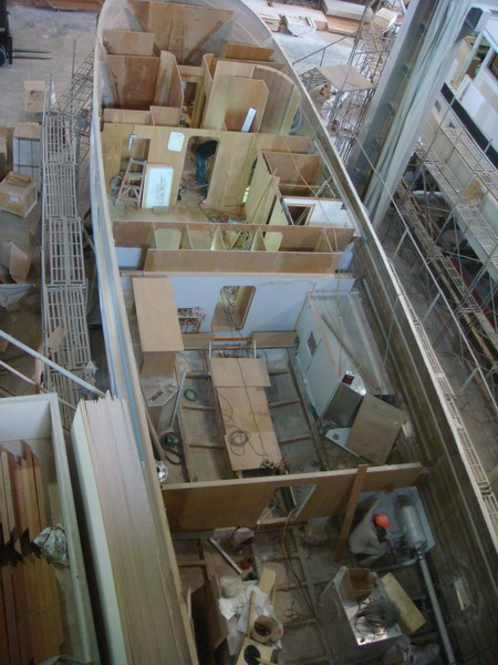
Friday, May 31, 2013

Construction: Week 23 - Significant Accomodations Progress

The Week 23 photos show considerable progress especially in the accommodations section forward of the engine room.  Here's a case where you will want to click on the photo below, which will expand the photos.  Then use the left and right arrows to switch between Week 23 and Week 22 overviews to see the progress.

Week 23. Overview
Week 22. Overview for comparison
Here's an explanation.  Bulkheads (walls) are going up.  This is evident to port immediately behind the VIP.  There we can see the enclosure of the 3rd stateroom, which as mentioned in previous articles houses the two bunk beds.  This stateroom also has a hanging locker on its forward bulkhead. 

Note: The bulkheads are made of marine plywood at this stage.  A veneer of varnished teak will be applied as the finished layer.

Use the 3rd stateroom as a starting point.  Just forward of it is another bulkhead.  That is the port side hanging locker for the VIP stateroom. Just aft and to the right is the cabinet for the washer and dryer (that are stacked one on top of the other).  Just to the left of the "laundry room" is space between the bulkheads for the storage locker that is accessed through a door in the master stateroom. 

Now move just to the right of the 3rd stateroom.  Two door frames are visible.  The one in the center is the door to the VIP.  The one to the right is the door to the guest head, which is now enclosed.  The bulkhead just forward of the guest head is the space for the VIP's starboard side hanging locker.  Compare Week 22 to Week 23 for this area and we can see that the guest shower structure has disappeared behind the stairwell structure.

Moving aft from the guest head we can see the round bulkhead for the stairwell that leads from the pilothouse to the accommodations.  Just aft of that is the structure of the locker that sits immediately across from the "laundry room."  That locker has shelves for a linen closet and a drawer at the bottom for laundry detergent, etc.

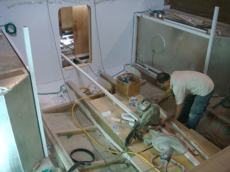
Moving aft to the master stateroom and focusing on the starboard side we can see the walls for the master head just forward of the white fiberglass shower enclosure.  Just to the left of the shower enclosure we can see cut outs for four doors, which are shown in the photo below.  From starboard to port (i.e., left to right) we see cut-outs for the starboard side handing locker, the door to the engine room, storage locker (which will have shelves) and finally the port side hanging locker.

Week 22.  Master stateroom looking aft.  door cut-outs are visible.
Next to the port side hanging locker and also in the lower left corner of the photo are the hydraulic stabilizer actuators.  The stabilizer fins will attach to the pins. These will be mounted pin down outboard (i.e. close to the hull sides) in the port and starboard hanging lockers.  The connection for hydraulic lines in visible on the port side actuator.  Also visible are insulated water lines for the chilled water air conditioning unit.

Explanation Note #1: Stabilizers are fins mounted beneath the waterline and emerging laterally. They are gyroscopically controlled with the capacity to change their angle of attack to counteract roll caused by wind or waves acting on the vessel.  Fins work by producing lift or downforce when the vessel is in motion. Effectiveness is increased as speed increases.  The photo below shows the actuator attached to the fin.


Explanatory Note #2: A chilled water air conditioning systems consist of the chiller, located in the engine room, that cools (or heats) fresh water, then pumps it through an insulated piping loop to air handlers located in the living spaces, where the air is cooled (or heated).   Click below for a diagram.  Chilled water A/C is an alternative to having multiple A/C units for each room as we did on the 48.  The 63 would need at least 5, which would occupy considerable space in the lazarette.

http://www.dometic.com/e93e31e2-2ac4-4704-90e2-00166d9d518e.fodoc

The perspective in photo below is from the master stateroom looking forward.  Here we see a worker installing steps for the stairwell.  Immediately to his right is the storage locker (for linens).   you can see wiring chases on the hull sides through the opening to the right of the photo.

Week 23.  Master stateroom looking forward to the hallway
In the photo immediately below we can see a glassed in bulkhead and insulated water lines for the chilled water A/C system.  The next photo shows the structure for the stairwell on the starboard side.

Week 23.  Glassed in bulkhead and chilled water system lines
Week 23. Notice the stairwell structure sticking up on the starboard side
Moving aft to the engine room.  Notice the structure on the port side of the engine room bulkhead.  That is the beginning of the fuel manifold or stated another way, the fuel management system.  The feed lines from the 500 gallon main fuel tanks are yellow and the return lines are red.  The manifold contains shut off valves that will enable me to manage the fuel system.  Notice the yellow lines leading up and over the tanks.  These are the feed lines from the two 150 gallon auxiliary tanks located in the lazarette.

Notice also the pipes at the top front of either tank.  These are the upper mounts for the sight glasses that enable you to see the fuel level in each tank.  The 63 will also be equipped with a fuel polishing system.

Week 23.  Engine room looking forward.  Note the fuel manifold system to port
Explanatory Note: A fuel polishing system is especially important in a trawler holding 1,300 gallons of diesel.  Here's why.  Diesel fuel, unlike gasoline, can support microbe growth.  When allowed to sit for extended periods the fuel can become contaminated with microbes (i.e., yeast, algae, fungi and other organisms).  This is especially true in warmer climates.  Condensation also produces water.  Combined with water, the microbes produces colonies and over time these living creatures die and fall to the bottom of the tank.  The result is a sludge like substance that clogs the fuel lines literally stopping fuel flow.  Water itself can damage the fuel injection pumps.

Diesel fuel contamination is a MONUMENTAL problem.  There a four solutions, three of which are either lousy and expensive.  Filtering the fuel is one.  In this case the fuel in pumped out of the tank through a filter to remove the contamination and then pumped back into the tank.  Problem: The contamination cannot be removed from the fuel lines and the contamination grows back into the tank.  A friend used this solution.  He paid $2,000 for the "treatment."  Four months later he lost an engine while cruising.  The sludge had returned.  Incidentally, the sludge collects in the off-engine 20 micron filters system and 2 micron engine fuel filter.  It literally looks like black sludge.

Cleaning the tanks and fuel lines is another option.  In this case, the fuel is removed and the inside of the tanks is accessed through a cleaning port or, one is cut into the tank if not included as standard equipment.  This is still problematic due to tank baffling, which restrict ability to get to certain areas.  This option is far more expensive.  Unfortunately, contamination can return if you do not get 100%.  Even if you do, the problem can return if the boat is not used enough.

Replacing the entire fuel system (tanks and lines) is the most expensive option and still not fool proof if the boat sits for extended periods.

The best solution is a fuel polishing system.  Essentially, this is a pump attached to the fuel manifold that continually pumps fuel through a filter system that removes water, microbes and dirt thus preventing contamination.

Side Story: It is also possible to get "bad" (contaminated) fuel from a marina, which happened to us in 2005 when we were cruising on our 1993 Sea Ray 440 Sundancer.  Unbeknown to us, we took on the bad fuel in Manistee Michigan.  We then proceeded to cross Lake Michigan (a 100 mile run).  While crossing I noticed the RPM fluctuate, first a 50 RPM drop and then occasionally a drop of 100.  The next day we cruised further south until when off Racine we saw the fluctuations increase dramatically (i.e, a 1,000 RPM).  We limped into Racine where a technician confirmed fuel contamination.  We replaced the Racor 20 micron filters and the engine's 2 micron fuel filters and went on our way.  The tech advised us that several filter changes would be required before the problem was solved.  We never found out as we traded the 440 for the 2006 Sundancer.

Returning to construction progress.  Below is a photo of the engine room looking aft into the lazarette.  Here you can see two rectangular holes on either side of the door.  These are for the sleeves where the shafts exit the transmissions to connect with the props.  Outer Reef installs Aqua Net 22 stainless steel shafts with two Tideless dripless shaft seals, one as primary and one as a back-up.  This strategy enables shaft seal replacement without having to haul the boat and remove the shafts.  Note the stringers just forward of the shaft holes.  These are shaped with a depression for the shafts as they exit the transmission.

Also visible in this photo are the pipes for the mufflers along with the supports for the 16 KW and 12 KW generators that were installed earlier.

Week 22.  Engine room looking aft
Diagram: Engine Room and Lazarette
Speaking of mufflers.  Looking at the lower right side of the overhead photo below and we can see a worker installing the muffler and exhaust pipe, which exits on the transom just above the water line.  Notice that the 150 auxiliary fuel tank sitting to the worker's right.  The auxiliary tanks will be mounted adjacent to mufflers toward to centerline.

Week 23.  Overhead photo.  Note the muffler on the starboard side
Work is progressing on the hull.  In the photo below we can see that a coat of Sea Hawk primer has been applied below the waterline (4 more to go).  I've included last week's photo for comparison.

Week 23.  Primer coat has been applied
Week 22.  Hull prepared for the primer coat (for comparison).
We also have photos from the carpentry shop.  Below are two photos of the half round that sits over the master berth.  We can see progress by comparing the photos.

Week 23.  Half round over master berth showing some varnished teak
Week 22.  Half round for comparison
We also have a photo of the king size master berth with the top removed.  The shop is installing the lip that holds the mattress in place.  In the photo we can see the openings for four drawers.


Needless to say, we have made considerable progress in 23 weeks. 

Week 1. Workers laying-up fiberglass
Coming soon: We attend an Outer Reef Rendezvous in Charleston, SC.  Expect photos of many Outer Reefs.  Also, we are looking forward to engine installation in perhaps 3-4 weeks.  Stay tuned.

Written by Les.

Saturday, May 25, 2013

Construction: Week 22 - Salon Extended with 3rd Window

As readers now know, Friday photos are additive and usually arrive around 8:00 am.  When, at 10:00 am, they were still missing I called Outer Reef where I learned that Jeff Druek was in Australia at a boat show.  Sure enough the photos arrived at 7:30 PM, which means Jeff emailed them when he got up.

Progress.  Starting with the "big" pieces.  The yard is still working on the hull as indicated by the blue masking tape, which seems to change locations from week to week.  We can see the bow thruster tube and the area below the waterline prepared for the expoxy primer (5 coats).  The yard has also errected extensive scaffolding.

Week 22.  Starboard side showing bow thruster tube

Week 22. Extensive scaffolding
The biggest change to the biggest pieces appears to be to the superstructure, which was removed from the mold last week.  Three salon windows are now visible indicating that the yard made a cut just aft of the second window and added a section effectively extending the length of the salon by approximately three feet. 

Note: I cannot, at the moment, explain how that section was added.  The question I've asked is how do you add a section and retain the superstructure's structural integrity?  My assumption is the "add-on" has to have some integration into the existing structure.  It can't just be glued on.  Stay tuned.

Explanatory Note (added on July 12): How the third window was added to the house. Adding a fiberglass section is a major project requiring engineering and a high skill level.  The builder essentially cuts into and partially destroys the original section. To be sure that the modified section won’t leak at the seams, the new extension must be molded with the existing section to create a new, unified structure. This requires cutting a wedge shape to the two sides and relaminating the parts on either side.  The finished lamination of the joint will be thicker and stronger than the original lamination.

Week 22. Superstructure showing three salon windows
Week 18. Notice that the salon has only two windows.
Recall that the 63's superstructure is derived from the 58's mold.  It is used on the 63 Cockpit Motor Yacht without alteration.  The "stretched" version is used on the 63 Long Range Motor Yacht.  Below are photos for comparison.
63 LRMY showing three salon windows
63 CPMY showing three salon windows
Progress is also evident below decks in both the accommodations and with regard to mechanical issues.  We'll start with the accommodations.  Recall that last week they had completed the flooring in the master stateroom.  This week's photos show that the areas forward of of the master are now floored.  This area (moving forward to aft) includes the VIP (V-Berth), guest stateroom to port (bunk beds) guest head to starboard and lower hallway with its locker for the washer and dryer.

Week 22. View from the VIP looking aft.  Note the round section
The round wall section in the photo above is the curved bulkhead for the stairway from the pilot house.  In the photo below we can see that the forward bulkhead in the VIP is glassed in and the exposed hull has been coated with an epoxy sealer.

Week 22.  Looking foward into the VIP
In the carpentry shop we now have a photo of the half round that will installed over the master bertth.

Week 22. Half round over the master berth

Master staeroom showing the half round over the berth
Work has progressed on the steering posts and the structure that will house the steering arms.

Week 22.  Lazarette looking aft at the rudder posts and steering mechanism housing
A comparison of the overhead views from this week and last week also show that work in progressing although its difficult from the photo to be exact as to what is happening.  That said, the "mess" suggests progress as it is not likely that they are using the inside of my hull as a trash barrell.

Week 22. Overhead view
Week 20.  Overhead view for comparison
Written by Les.

Friday, May 17, 2013

Construction: Week 21 - House Out of the Mold

Friday photos have arrived.

The big news is the superstructure is out of the mold.  The photo below shows it upside down on the shipyard floor.  We are looking from the bow forward.  The open space to the right (starboard side) is the door from the Portuguese bridge to the bow.  The pilothouse windshield and bow seating area are also visible as are window blanks for the salon (if you look real hard).

Week 21.  Superstructure out of the mold and upside down
Below is a photo of the finished product showing bow seating just forward of the Portuguese Bridge, the door and the pilothouse windshield.


Finished bow seating and Portuguese Bridge
In the photo below a worker is doing something on the starboard side of the hull, which could be touch-up to imperfections in the gelcoat - no big deal.  The port side of the photo shows the fiberglass structure that will house the 12" bow thruster and the tube itself.  The area below the waterline is being prepared for the five coats of epoxy primer undercoat.

Week 21.  Port side view of the hull and bow thruster tube
Work continues inside the hull.  In this overhead view we can see that fuel tanks are partially insulated.  We can also see the fiberglass showers stalls installed several weeks ago and the uninstalled auxiliary 150 gallon fuel tanks in the lazarette.

Week 20.  Overhead view
Closer inspection of the engine room shows the insulation around the fuel tank and copper bonding strips running along the stingers.

Week 21. Engine room looking forward
The photo below shows the engine room looking aft.  Notice the hole in the bulkhead for the port exhaust tube.  We can also see another hole for a wire chase.  We can also see boards that provide the platform for one of the two generators.  The 12 KW generator will be mounted to port.  The 16 KW generator to starboard.
Week 21. Engine room looking aft.
Work is also going on in the lazarette.  We can see a worker putting in place structure for the rudder control arms and we can see the rudder posts. Copper bonding strips are also visible along the stringers.


The floor is now installed in the master stateroom.  In the photo below you can see hot and cold water runs taped to bulkhead and wire loops along the back of what will be the starboard side hanging locker.  It appears that the hull sides have been sanded in preparation for the final white epoxy paint that coats the fiberglass.

Week 21. Master SR looking to starboard
The photo below shows the master stateroom looking to port.  We guess those are the fiberglass frames for the shower doors.
Week 21. Master SR looking to port with plywood sub floor
Finally, we have another photo of the VIP queen sized berth and for comparison the finished VIP stateroom.

Week 21.  VIP queen sized berth
Finished VIP stateroom.
Written by Les.

Saturday, May 11, 2013

Construction: Week 20 - Concurrent Carpentry

Here are today's "Friday" photos.  My first impression was that not much was going on.  I changed my mind after chatting with Mike Schlichtig.  The changes are subtle and in some cases you will have to look hard but it is clear that progress is being made.

Now we have photos of concurrent work going on in the carpentry shop.  The two below show the platform for king size berth in the master stateroom and the queen sized berth in the VIP (aka V-berth).

Master SR King Size Berth.  Note the venting for the sub woofer
VIP Queen Sized Berth
Work is also progressing in the engine room and in the accommodations. 

Overhead view of lower deck showing worker in the engine room
Let's start with the engine room.  For comparison I've included a photo from last week to allow you to better see the changes.

Week 19. Engine room photo showing insulation on the floor just aft of the forward bulkhead

Week 20. Worker fabricating the framework for fuel tank insulation
The photo shows a worker fabricating the frame that will be used hold the sound proofing insulation structure around the fuel tanks.  This is the same multiple layer insulation structure used on the bulkheads and ceiling.

Also note the green wire running from the inspection port (round circle) on the starboard tank and along the frame adjacent to the forward bulkhead.  You can also see wire running from the port tank.  That "green wire" is bonding cable that will ultimately connect the tanks and all other metallic components to the "Central Bonding Strip" whose role is to prevent electrolysis.

Explanatory Note: Electrolysis is caused when an external current, called a stray current finds a path between two metals in the presence of an electrolyte (water and moisture). The two metals may be of exactly the same type or different types.  If the stray current is sufficient to overcome the natural galvanic current then the more noble metal may well become the anode and is thus destroyed. The rate of electrolysis attack is dependent on the amount of current present. A stray current caused by a short circuit can ‘eat’ metal components away in a very short period of time.

Finished engine room looking aft
Now we move to the accommodations.

The photo below shows the master stateroom.  Here's how to understand the photo.  The partition in the upper left delineates the one of the two hanging lockers.  At the upper right is the edge of the fiberglass shower. In the center of the photo under the sub-floor is the 300 gallon water tank.

Week 20.  Master stateroom looking to starboard
  with plumbing visible
Notice the blue hose toward the back of the tank.  That is the cold water PVC piping running to the shower.  That hose connects to a water manifold (distribution point), which connects to a fresh water pump and then to the water tank itself.

Clicking on the photo will cause it to expand so you can see more detail. To the left of the water tank you can see framing along its side and immediately below it a red hot water hose.  There is also bonding wire that will connect the aluminum water tank to the "Central Bonding Strip."  The hot water hose also connects to the water manifold (distribution point).  Before that it connects to the 20 gallon hot water heater located under the floor in the next compartment.

Immediately adjacent to the hanging locker bulkhead you can see a wide black hose.  That appears to be the drain hose that will eventually be connected to the commode in the master head.  That hose goes directly to the boat's 100 gallon black water holding tank.

The photo below is the master stateroom looking to port.  Expanding this photo will allow you to see wiring hangers that run along the frame on the port side of the water tank.

Week 20.  Master stateroom looking to port
The sub flooring will eventually be covered with marine plywood.  On top of that will be a thin rubber mat to hold the carpet in place.  Unlike a home, the carpet is not nailed to the floor.  It must be removable to gain access to numerous hatches which provide access to equipment (e.g., grey water pumps) and the ability to check the bilges.

Notice the red toy car in the photo.  My best guess is that it is a radio owned by a worker.  Otherwise, I have absolutely no idea why it is there.

Finished traditional master stateroom
Written by Les.